Rendering Basics
BamBozzle
This section will walk through the process of rendering a 3D triangle, given its point in 3D space. This step is broadly the same regardless of the method of rasterization you are using, though there may be slight differences from engine to engine1
Projection
Reference: https://youtu.be/tX_x4iYvspU?t=128
Firstly, we must define a list of triangles. All models are composed of many interlocking triangles in a space, called model space. Each triangle also consists of three vertices. The way the triangles are defined by these sets of vertices is by using a list of indices that point to which vertex it will use.

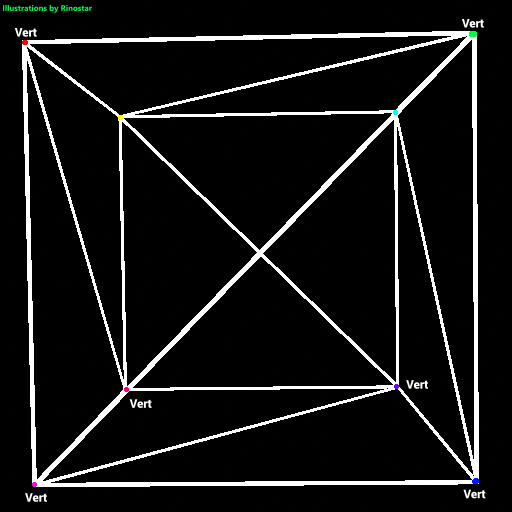
Here, I’ve shown what a cube would look like if we just rendered each edge of the triangle. I’ve also made colored dots, and text around them showing where each vertex is. As you can see, a cube has 8 vertices, and 6 faces. But, since this is composed of triangles, the cube has 12 tris2. If we were to just have each triangle have its own set of vertices, the renderer would have to do extra calculations to project the same vertices if these triangles were connected. That’s why indices are used. Here’s an example of this cube being represented in a mesh file:


As you can see, each vertex has a 3d point in space. This is usually represented as either coordinates, or vectors. Of course, all coordinates can be vectors, but not all vectors can be coordinates.
Above you can see the list of face data as well.
This entire code for just the cube model is pretty long, especially when you try to stuff vertex colors, uv data, and more inside each model, but that’s how it works. You can plainly see that each face has 4 numbers. The first 3 are pointers3, or indices to the vertices of the mesh, and the fourth one is just what color the face is. We won’t be covering face color yet. When getting model data, it’s generally a good idea to have your indices and vertices in separate lists during runtime. The reason I stored the mesh data like this is simply because of being able to more easily import meshes before running the engine. Plus, the mesh data just gets split into vertices and indices whenever needed. But what do we do with all this data?
Well, if you're just making a mesh loader or something similar, you can just skip these steps, but if you want a more advanced rendering engine (which can be turned into a game engine later), this step is nearly essential: we will need to project these meshes into world space. The reason for this is to be able to not only have multiple meshes rendering at once, but to also be able to freely move, rotate, and scale them at will.
Converting to World Space
So how do we do that? Well, with some vector math, of course! Expressing the scale matrix, which allows you to be able to stretch or squeeze objects in any axis, it looks like this:
.
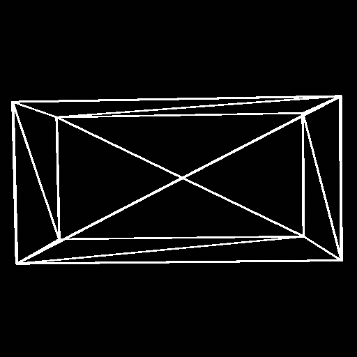
Going back to the cube example, if we applied the scaling matrix, with S = [2 1 1], then the cube will turn into a rectangular prism:

Next, the translation (or the moving thingy around) matrix. This is very weird, but here it is:
.
This matrix makes use of homogeneous matrices. I won’t go into detail here,4 but this just lets us have 4x4 matrices in 3d space. This will make translation possible, though. Next up, the rotation matrix. There’s already a page for that explained here: rotation matrix page in the book (pg. 13), so I don’t actually have to show it here. There’s also more talk about it later on, too. So now we know how to project the vertices to world space using math, but how do we implement it into scratch? Well, first we’ll have three variables, x, y, and z. This’ll be the variables that get transformed through each matrix. Note that the rotation will be in three axes in this case.
Each matrix is its own function, so here’s the scaling function:
It’s very simple, it just multiplies each component with the corresponding scaling component. Next up, the rotation triples!
They all look similar, except which variables are affected, and which components it uses.
Very simple, just a bit of trigonometry, though.
And finally, the translation function!
Also very simple, just like the scaling matrix, except you add the vectors together. And with that, you can position any 3d mesh into world space. Note that when trying to put multiple meshes into the world, you have to store the current length of the world vertices list (if all three components are stored in that one list, and you usually either skip indices to get each vertex, or you multiply the index, just make sure to divide the length by the number of components, which in 3d is 3) as a variable like Lv, and when you copy over the new indices, just add the indices with Lv, so as not to create something I like to call, face interference:
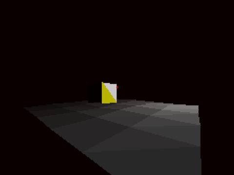
offset off:

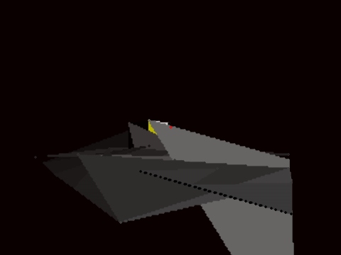
offset on:

(In this case, offset is the variable to add with the indices for the mesh)
Next up, converting the entire scene in world space to view space.
Converting to View Space
Z clipping
Filling
Rendering n-gons
Krypto
One way to raster a polygon is with the fan triangulation. The way this works is that you “pin” one of the vertices of the polygon and then you go around the polygon creating triangles with the vertices of the pin and the current one you are looping around. As you can see in the image below, this triangulates the polygon. Furthermore, you can use quads in a painters engine to triangulate this polygon, adding a bigger performance boost when rastering polygons. This method of triangulation only works with convex polygons, however.
Some engines choose to perform the projection step before the sorting step when using painter’s algorithm.
tris will be short for triangles.
In c, or c++, you already know what I might be talking about.